Thursday, 28 November 2019

CPP- Co generation Power Plant

CPP- Co-generation Power Plant.

I spent some good amount of time in Thermal Power Plants.I will try to give you a brief idea on the same.

CPP is nothing but a Power plant which is a facility that is built in plant per-misses for supplying the power requirements for flagship products. Definitely would be much inexpensive price of 3.5 Rs/KWH to 4.5 Rs/KWH than grid supplies which is around ~6 Rs/KWH to 9 Rs/KWH tariffs may change from state to state...which is generation cost for a CPP... This may also study on the abundance of natural resource like water and coal which are the main inputs for Thermal Power Plants.

There will be only two broad areas in power plant Turbine area and Boiler area. There is a plenty of material for process understanding of thermal power plants in internet.So lets only focus on cost point of view and some main parameters which will define the performance of Power plant.

Coal:
In a normal scenario 0.8 to 1 Kg of  coal will consumed for producing 1 KWH of Power... REALLY!!! Yes most of the Power plant companies knows it because of Ash% which will be around 25% to 40%.So credit is Ash can also be supplied to Cement industry and also as a brick production.
That says 0.5 Kg which is of 1 Pound is ideally required to produce 1 KWH.
People will blend different types of coal for optimum results.

TG Heat Rate which is the Thermal to Electrical Energy ratio decides the efficiency of TG Set. Which ideally needs to be minimum. What i observed is it will be around 2500 Kcal/KWH to 3000 Kcal/KWH...So coal GCV is the one which can enhance these numbers which is having a range of (3200 Kcal to 3900 Kcal).
Station Heat Rate is TGHR/Boiler Efficiency ideally people expect 100% efficiently the boiler should run. But may possible if we use Direct method calculations.

Water:
From where DM water is prepared...which is ultimately used for steam production.Online sensors and lab test for water like Ph,Conductivity is the main parameters under the scanner for performance improvements in Thermal Power Plants.

Auxiliary:
Means Supporting equipment to handle water, coal and air. like BFP,PA FAN,SA FAN,ID FAN etc.
People will definitely focus on reducing this because there will be around 10 to 15% auxiliary consumption when compared to Production. So nearly 1 MW for every 10 MW Production.
Right ratios and loading will decide minimizing the % consumption of Auxiliaries.




Thursday, 6 September 2018

How to Understand Historian Basics

I spent some good time with Historians implementation using Aspen IP21....

Historians are time series databases which will store plant data from all units in a "centralized repository" ..from where users can visualize,Analyse various units/plants control system data in a structured way from their own desks... which ultimately useful for "Strategic Decision makings"...and also as a "real time monitoring system" which is also called "RTMS"...

Our Clients major focus was to reduce "Power Consumption" with out effecting Production and quality.

This software answers how to improve either Production/Quality/Save etc using your own data.. And at least it will take you to "2 Whys" based on the dashboards/Fault trees developed.

Once the system is enabled people will have an access to visualize historical data...from their own desks through either a web link which is called Aspen Process Explorer/a1PE..or through a a1PE desktop client itself...

" a1PE" itself have many statistical functions where analyst or process engineer can export the data in various forms for regression analysis or correlation analysis of dependent and independent variables..List below are some of the features of a1PE.

  1. Statistics features like Regression, Mean,Median,Standard Deviation,Averages etc..
  2. Exporting data inform of tables to excels.
  3. Comments/Annotation can be set on trends. 
  4. Alarms can be set with auto email feature is available in a1PE...
  5. Adhoc Calculations can be done on the fly using tags.
  6. Reports automation like daily reports  shift reports etc.. 
There are various advantages once this Historian is implemented...few are listed below ...
These reports automation will more successful if plant have a maximum online metering which will fetch data from transmitters/meters..
  1. Automating Shift reports,Daily reports,Monthly reports,
  2. Performance reports of an equipment,
  3. Dashboards for real time monitoring for Production/Consumption/Stock/KPIs/Fault trees/Environmental etc..
Calculations can be build on the fly using "Aspen Calc" and store the information in a Tag..

Dashboards can be developed using "Aspen Graphic Studio Browser" where it has a various features like a dial gauges,input boxes,bars,graphs etc...

How Data flows:
DCS/PLC Control Systems To OPC To ASPEN IP21
"CIM-IO Interface" installation in OPC machines which acts as a TCP is an interface which sets communication between OPC and ASPEN IP21..

Some of the DCS Vendors like Honeywell,Emersion, FactoryTalk,Schneider etc...

"Aspen Administrator" Which we do maximum of the work like Repository Creation,Analog/Discrete/Text tags creation with all the properties like description,units,limits,OPC path mapping,

Major Components of Aspen IP21 which are listed below...
  1. "CIM-IO Interface"
  2. "CIM-IO Connection Manager"
  3. "Aspen Administrator"
  4. "Aspen Graphic Studio Browser" 
  5. "Aspen Calc"
  6. "a1PE or Aspen Process Explorer"

Definitely the process will be same in any historian...Some of them are
OSIsoft PI.
GE Historian
Factory Talk SE Historian


Saturday, 28 July 2018

Sequence involved in Thermophysical properties(Fixed Properties and Temperature Dependent Properties) in Chemical Simulation Software

I have been reading some excellent literature where I tried to learn sequence of calculations involved in Thermophysical properties.

Let's start with assay processing where from TBP curve we will get Normal boiling point, composition and specific gravity as out put for each cut components.
Additional reading : Mid point average and LV% method, Watson K factor /Charecterization factor equation.  Where these methods used to convert curve to pseudo components as per cuts defined.All these methods uses boiling point and Gravity as main input.
Reference: Characterization of Petroleum fractions by Dr Qaiser Muslim Abid Ali Assady. And Characterization of Petroleum fraction Hassan S Nazi.

Now think like we have Normal Boiling Point and Gravity for each pseudo component.

Now we have to calculate Critical properties (Tc, Pc, Zc, Vc, Acentric factor)
All these fixed properties are derived from either RIAZI Dubert, Cavet 1962,Cavet 1980,TWU..  I calculated using RIAZI Dubert we got a good match however TWU is suggested because it will do some back calculations to check whether calculations are correct.

Now Temperature dependent properties at desired temperature.  Vapor Pressure (extention of Antoine equation), Acentric factor (depends on reduced  vapor pressure pitzer Correlation) .
 Density(from eos by eliminating V) Vapor pressure(extension of antoine - reidal) , Enthalpy (yan Alexander and Lee kessler,  William for solid H) .I got this understanding by reading one paper ( Thermophysical properties of UF6 which are required for stress testing when engraved in fire where literature data is not sufficient to calculate at higher Tr and Pr)

Note :
This is only for theoretical purpose only.  And there is no guarantee on using for research / any other purposes. 

Sunday, 29 April 2018

What is Fouling and monitoring parameters involved and when to clean Heat Exchangers.

Fouling: The deposition of undesirable material on the surface of tubes/shells on an Exchanger.

From Historian data if you find cascade controller at Heat exchanger flow valve is fully open/Max Limit to maintain the outlet temperature then you should act.
Means temperature is maintaining and flow is increasing continously then we have to pay attention.
Even though if we don't have cascade arrangement there will be atleast flow controller so it is very obvious if temperature reduces we increase the hot fluid / steam flow.
Problem: Heat exchanger Fouling.
Monitoring data :Flow Control valve opening/flow and outlet temperature of exchanger.
In general a cascade range controller will be used for the exchanger to maintain outlet temperatures. Arrangement will be like this.


Why at this condition we have to send for maintainance...  read below.

I was reading an excellent blog...

https://eng-software.com/about-us/press/articles/managing-heat-exchanger-fouling-to-reduce-risky-conditions/
I have extracted some information from that article.
"
At a constant flow rate, as fouling occurs and the resistance to heat transfer increases, the heat exchanger’s heat transfer coefficient (U) decreases and will result in:
  • a lower heat transfer rate
  • a higher outlet temperature on the hot side (and lower dT hot)
  • a lower outlet temperature on the cold side (and lower dT cold)
Since the outlet temperatures of the hot or cold side may be critical to the quality control parameters for the overall process, the flow rate must be increased to achieve the desired heat transfer rate and outlet temperature. A higher flow rate reduces theconvection heat transfer coefficient (hffor the fluid and increases the overall heat transfer coefficient (U)to compensate for the effects of fouling. Very often in these applications, an automatic process control loop is used to measure and control the outlet temperature of one side of the heat exchanger by regulating the hot or cold side flow rate with a control valve (and occasionally a centrifugal pump operated by a variable speed drive).
"
**** Under Construction ****

Friday, 24 November 2017

Working of compressors and expanders and importance of Moeler Diagram

Moiler diagram and working of compressors and expanders.

This diagram plays an important role in calculations of outlet conditions like Temperature, Pressure (generally an input), Enthalpy and Entropy of compressors and expanders.


Which inturn helps in calculating work performed by the compressor..

Please note compressors and expanders works in Isentropic flash conditions means Entropy is constant both PH(Pressure Enthalpy) and (Pressure Entropy) Calculations will be done on this object.

Some other objects and corresponding flashes.
Headers- RhoU Flash
Drums-Pressure Internal Energy flash.
Exchangers - PT Flash.
Valves/Pipes - Isenthalpic -  with knowledge of this by knowing outside pressure of valve it is possible to calculate temperature and velocity through valve

To be continued.. 

Monday, 20 November 2017

Basics of Fluid Mechanics and how it is helpful in simulation(Part1)

Topic1:
Basic Equations:
Lets start with a continuity equation which is A1V1=A2V2 , if area(A) is small the velocity(V) will be more, application would be gardening pipe..


There is an extension of this equation is Bernoulis Equation most famous energy balance equation.

P1+Rho1*g*h1+1/2Rho1*V1^2 = P2 + Rho2*g*h2+1/2Rho2*V2^2

1st term is pressure energy term , 2nd term is potential energy term and third is kinetic energy term.
Pressure in Pascals,
Density in Kg/m3,
Velocity in m/s,
h1 in meters,
g is 9.8m/s^2.
This equation can be modified in to simple cases i.e many terms will get cancel according to the given problem..

One example is if inlet and outlet of a pipe is in a same height then Potential energy term will cancel out.
P1+1/2Rho1*V1^2 = P2 +1/2Rho2*V2^2

Second Example is Leak from a tank: V1(Velocity of tank) =0 because the fluid wont move and only the V2 is in motion.
P1+Rho1*g*h1 = P2 + Rho2*g*h2+1/2Rho2*V2^2
If the tank is open to atmosphere then pressure terms will get cancel.
Lets do a simple example,
Inlet conditions of water flowing in a pipe with a conditions of 1.2 m/s and having 130 Kpa and its height is 2m and the outlet of the pipe is at 4m height and the outlet velocity is 7m/s. Calculate Outlet pressure.

It is at certain height and the velocity is more so we can say the outlet pressure will be less

130000+1000(9.8)(2)+1/2(1000)(1.2)^2 = P2 + 1000(9.8)(4)+1/2(1000)(7)^2

On substituting we will get P2 = 86.62 Kpa which is lower than the inlet pressure.

Continuity and Bernouli equations are basic equations that are used in calculating Flow meters velocities (Venturi / Orifice meter).

How to find pressure drop if U tube Manometer is installed and we know reading of Manometer.
Delp=delrho*g*h this is similar to rho*g*h

Here h is the Manometer reading.
In general, fluid in U tube Manometer will be Mercury, density of Mercury is 13600kg/m3.
-------------------------------------------------------------------------------------------------------------------
Topic2
Pumps: The objective of pump is to trasfer liquid from source to a destination.

This may be filling a tank at higher level or circulating a liquid. In both the cases pressure is required to make this work.. This is generally referred as HEAD.

HEAD = STATIC HEAD + FRICTION HEAD.

Head(feet)/2.31 = Pressure(Psi).

Please Note: Supplier/vendor terminology is HEAD and users terminology is pressure.

STATIC HEAD is the vertical distance that the liquid has to be lifted.
FRICTION HEAD is due to the fittings and size of the pipe.

The centrifugal pumps which generally creates energy due to rotation of impellers - the created energy is converted in to fluid pressure.

Pump power is P = delp*Q/eff

Q in m3/sec
P in Watts = kgm2s-3
Pressure in Pa = kg/m. s2
Eff is efficiency.

DelH = delp/rho

In steady state simulation inlet stream conditions will be given(pressure, temperature, flow  and composition) and we can provide outlet pressure or pressure rise or pressure ratio and efficiency in pump Unitop, the simulator will predict required power. This is the basic equation.

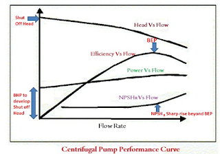
In dynamic simulation we generally provide curves, head vs flow and efficiency vs flow/power vs flow. And when pump is running at its design conditions we verify the power / efficiency.


Pump Curves:
There are 4 types of curves related to pump,
1) Head vs Flow,
2) Efficiency vs Flow
3) Power vs Flow
4) NPSH Required vs Flow

Pump Curves data extraction in OTS modelling is one of the most important work to get a proper discharge pressures of the pump.

In general there will be controller (Indirect action ) arrangement at the minimum circulation line, unless the flow develops the pump will be in minimum circulation. If flow starts developing the forward flow controller will start opening The forward controllers has to kept in auto which is a direct action controller.


When you need additional head use pumps in series and when you need additional flow use pumps in parallel arrangement.
Affinity Laws:
Volume Proportional to Speed
Head Proportional to Speed2
Power Proportional to Speed3

Small change in Speed can give significant change to the parameters.
----------------------------------------------------------------------------------------------------------------------
Topic3:
FRICTION HEAD -> Calculated based on Darcy Equation.

Darcy friction factor =4f

Hf= fd* L/D * V^2/2g

Hf-> Friction Head in Meters.
f ->fanning friction factor,
D->Pipe Diameter,
L->Length of the pipe.
V->Mean velocity of fluid.

Head loss due to fittings is calculated based on K Method.

H_fittings = K V2/2g

Example the K value for 90degree elbow having R/D=1.5 is 0.45. This is a long radius elbow.
Note: "K "value will be different for different fittings. In general these will be saved in softwares.
If fluid velocity is 4m/s
Then head loss due to fittings is 0.367m

Now the total head loss is Ht=H_fittings + Hf
For Laminar flow f = 16/Re
For Turbulent and e/d(Relative pipe Roughness)<0.001 we have f = 0.0079/Re^1/4
For greater values of e/d(Relative pipe Roughness) we need to use Moody Chart.

How to read Moody chart: 
https://www.youtube.com/watch?v=tISdp_394Bw


Steps involved in calculating Hf/Pressure Drop in a pipe is
1) Calculate Reynolds number-> Decide the region->if Re<2000 it is laminar or else Turbulent.
Ignore transition region.
2) Use the proper correlation/Moody chart for calculating f(friction factor)
and substitute all the value in Darcy Equation. to get the values like Hf and also Pressure Drop(Rho*g*Hf).Power required etc.

Simulators clearly mention the pressure drop is calculated based on Darcy friction factor.. Beggs and Brill is one of the Equation. As per these experiments they have divided in to 3 flow regimes, defined as segregated, intermittent and distributed flow - the term liquid hold up will vary based on three flow regimes

There Will be 3 terms in pressure drop calculations in a pipe..  friction, elevation and acceleration term. 


The drawbacks for this equation is.. it won't predict properly for high pressure gas condensate systems. As it is derived based on water - Air system. 

I think most important part is how Moody chart is converted to equation format.- Answer for this is there are many equations in literature to find the f in turbulent flow region one of them is
Colebrook - White Equation

https://en.m.wikipedia.org/wiki/Darcy_friction_factor_formulae


Reynolds Number = Intertial Force/Viscous Force = Rho*d*V/Viscosity

Rho in Kg/m3
d in Meters
V in m/s --> If flow rate is given divide it by cross section area to get in m/s
Viscosity in kg/m-s which is equivalent to N-s/m2 =Pa.s

1c.p = 1 Mpa.s = 0.001 Pa.s=0.001N-s/m2 =0.001kg/m-s.


Power units 1 Watt = 1 J/Sec = Kg m^2 s^-2
1 Hp= 736 Watts.
Valve coefficient Cv=q*(sg/delp) 0.5

Reviewed by Prof KV Rao

Friday, 7 July 2017

Group contribution method joback

Hi everyone this blog is about how pure components properties are calculated using the group contribution methods available.

There is nothing much to explain because Wikipedia covered about joback method to calculate the 11 properties and also given example for acetone.

The 11 properties are, Boiling point, critical temperature, critical pressure, critical volume, melting point, hformation, gformation, heat capacity, heat of fusion and dynamic viscosity

I am writing this blog,  is just for my practice for another compound namely methylchloride (CH3CL),  so CH3- is a paraffinic group and CL is a chlorine derivative. Here CH3 is one group and CL is another group. So we want to know how these two groups contribute to form a compound.

To begin with,  as explained in Wikipedia collect all the individual /group properties like critical properties tc, pc, vc, tm, hform, gform, and as per correlation just sum it and substitute in equation. In software's this groups data will be saved in databases.

 I have also compared with standard software as well. For my surprise I could able to match the compound  properties even in decimal level.


The advantage here is the correlations are very simple all we need to do is summation of individual group properties and substitute in correlations. All properties are calculated at standard conditions 1bar and 25degC.

Joback is an extension of lyderson who found relationship between boiling point and critical point. 

CPP- Co generation Power Plant

CPP- Co-generation Power Plant. I spent some good amount of time in Thermal Power Plants.I will try to give you a brief idea on the same....