Monday, 28 December 2015

Law of Diminishing Marginal utility in chemical engineering way


Utility means satisfaction by consuming goods or service or something else. An imaginary number or cardinal approach which is used to measure the satisfaction is called "util"

Utility can be seen in commodity angle and also from consumer angle but let us restrict the topic to above definition and continue.

Law of Diminishing marginal utility:

If you model a first column it will give you more satisfaction if you model the same model again and again and again by keeping other models like compressors in constant your total satisfaction will increase but marginal utility will decrease. so this is called marginal utility in chemical engineering way.

some equations if you want to see in graphical way Mu=DelTu/DelQ
Tu->Total Utility
Mu->Marginal Utility
Q->Change


so model compressor also in between so that you can consume different goods and you will get more satisfied.

---------------------------------------------------------------------------------------------------------------------
What a crap- If someone find the above content is this then i agree 100% YES it is a crap.
I am continuing the blog with out editing the above content as i find some mistakes in it and what i feel is mistakes are GOOD.Another reason is i am not an economist yet.

Basically as a consumer means in above example modelling engineer finds column and compressors as a big things in modelling point of view so there are some "assumptions" in Law of diminishing marginal utility i.e 1) The unit of consumer good may not hold if the unit is too big or too small. so in this case we cannot consider a "valve" as it is very small and "column/compressor" as it is too big in modelling point of view. Read the above statement considering Exchanger or a Pump instead of column which will give better understanding of law.
2) Mental condition of the consumer  must remain normal - There should not be additional pressures means you know how corporate runs.
3) There must be continuity in consumption where a break in continuity is necessary.
4) The consumer taste or preference must remain the same during the period of consumption.

Wednesday, 7 October 2015

REFINERY OVERVIEW


I thought to share this experience as i am working on project for a major refinery. contributed to various units.

I don,t want to replicate what is there in wikipedia and other sources what i will try to explain here is to give an overview of refinery and major issues that generally we face during dynamic model preparation.

Some Common observation:
Point 1:
                    Fractionator, Fractionator overhead section Fractionator bottom section.
Fractionator overhead section objective is to recover Naphtha and oils and Fractionator bottoms will go to another fractionator and process repeats twice means first is CDU or ADU second is VDU and third is DCU objective of all the three is to recover end products.

Overhead section will have treatment units like Amine absorber, one Stabilizer, net gas scrubber,Compressors to increase the pressure as to increase condensing temperature for recovery of end products like LPG,Naphtha and Oils.

Point 2:

Its all about proper data entry, configuring equipment's properly, and Thermo Thermo Thermo..

Thermo - What are all the things you have to see in general during fluid package selection.

Vapor fraction otherwise splits won't happen.
Densities it will create unnecessary problems during flow across ex changers, pumps with integrated models.
Psudo components selection and properties.
Separation - interaction parameters availability if not look for options.

:::::UNDER CONSTRUCTION::::


Thursday, 30 July 2015

How Relief Valve Sizing is done in Visual Flow

Relief Valve Sizing in Visual Flow.

This is one exercise which i have done in Visual Flow and to compare the results with under development software called SimCentral. It gave me great exposure to API520 standards and API 3 % Rule.So i thought to share my experience here.

Background of what Visual Flow is:

  • Relief valve sizing,Network analysis,depressurization etc can be done in Visual Flow. This is a product from Invensys/Schnider.
  • Visual Flow is a software which will give an error message to user if the valves doesn't meet API 3 % rule during rating.
  • Visual Flow is a software which have a great interactive ISOMETRIC drawing layout. Means we can exactly draw (changes in directions of  piping's and fittings) from ISOMETRIC drawings.
  • I am not that great in understanding  DIERS and OSHA compliance in software. But one thing i know is OSHA(Occupation Safety And Health Administration) will penalize companies/industries where relief valves doesn't meet the 3% rule during their inspection. This is the point which created interest in me.

Exercise:

  • I need to size a relief valve for 3 vessels which are maintaining at different pressures(LOW,MID,HIGH) for certain gas mixture.
  • Flow sheeting, Components, K Value method , Beggs and Brill for Pressure drop calculations method are selected same for both software's.


Differences in software's at that stage:
  • Inlet and exit losses of vessels are also selected k=0.5 & 1 (standard if i remember). and it is not present in Simcentral
  • ISOMETRICS interactive interface is present is Visual flow but not in Simcentral.
  • Standard Relief valve selection is present in Visual Flow based on Codes like 6Q8, Q stands for orifice area. But orifice area is input in SimCentral and no standard charts available. 6 is suction line size and 8 is the discharge line size. Check appendix for more information.
  • Sizes selected are different for all three vessels because sink/flare pressure is same but not the sources pressure.So when Delta P is large you need a big size valve to blow down that volume.
  • Visual Flow is having Sim4Me Thermo but Simcentral doesn't have means both have their local thermo systems so used local thermo for both software's.


The problems that i faced during this exercise is.

  • At the time of doing this exercises i don't have a proper ISOMETRIC drawings. So assumptions and API 3 % rule made me realize that why suction lines should be smaller and discharge lines in general larger. 
  • Point 1) We cannot have so many fittings in suction line.
  • Point 2) There has to be proper ratio maintained in Suction and Discharge lines.
  • Finally converged the flow-sheet.
Apart from this:

  • All i need to match is density,Molecular weight as a main property because Enthalpy datum will differ from software to software.
  • And most importantly blow volume. Slight differences observed in velocities hence slight differences observed in pressure drop in suction line and discharge because of unavailability of fittings with directions in Simcentral.
  • Problems faced at high pressure system so modified the Beggs and brill to modified Beggs and Brill method.
Who size relief valves:

  • There are EPC companies which maintains teams for sizing of relief valves in separate department with much more standards,Codes and using different software.


OTS Point of view :


  • From OTS point of view relief valve datasheet is used for modeling. mostly blow start pressure,density.
  • And testing will be done whether it is popping up or not when blow start pressure reaches and also testing will be done when blow is stopping or not when it reaches blow stop pressure(85% of blow start pressure based on standards)


Appendix:


Tuesday, 2 June 2015

Thermo selection options for highly polar components

Thermo selection options for highly polar components.

Based on my experience i will try to explain the various options available for thermo selection options when polar components come in to picture.

Note:Most of us know that there is no one such method which can satisfy all the conditions in plant. System to system and  condition to condition methods has to be changed.

So in below section:

  • Thermo methods for non polar or slightly polar components.-Eg: SRK, PR
  • Thermo methods for polar components.-Eg:IF LLE Systems like MTBE, UNIQUAC,
  • Few points on Accentricity, Molar volume,Heat of vaporization,Solubility parameters, Vanderwall Area, and Volume.
  • Few points on DIPPR database and how researchers help simulation engineers when dealing with polar components.
  • Few tips on how to know the two/multiple components are said to be misible and selection of best solvent with out doing any simulation.
  • Thermo methods options for polar components.

UNDER CONSTRUCTION:

Sunday, 10 May 2015

Psudo Components or Hypo components in Simulation


We came to a point where component databases in commercial simulators will have limitations and there are ways to define a components with some little effort.

So here i will try to explain what is that little effort has to be taken care for defining Psudo Components or Hypo Components.

This little effort will give an out of box thinking and you will realize that simulators are not just play stations.

I am referring one very good literature where petroleum characterization was explained in detail.
Characterization of petroleum fractions by Dr. Qaiser Al-Assady
I am also referring PRO/II application brief manual and software where we can actually generate the working TBP curve and all the options which are discussed in literature will be  available in PRO/II assay processing.

So in below sections:

  • Why Psudo Components or Hypo Components are so important.
  • What are inputs required for generating these components.
  • Alternate way if we don't have distillation curve data.
  • Briefly on ASTM Distillation curves.
  • Briefly on UNIFAC group contribution, SMILES etc,
::::::::UNDER CONSTRUCTION:::::::

Saturday, 9 May 2015

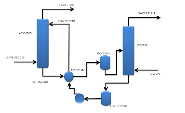
Modeling an absorbtion and stripping column


Generally you will observe these two columns together.


Absorbtion Column:

Purpose of absorbtion column is to react with one of the components in a mixture of fluid which will enter from the bottom of the column with an absorbent from top of the column so these two fluids come in contact counter currently.

In general abosrbtion favors low temperature , high pressure conditions and the streams which are coming in are to be maintained at same temperature.

OK but why we have to maintain same temperature?
Hint: Henrys Louis lechatilier principle.

If you observe the solubility curve the solubility increases with increasing in pressure which was drawn at "constant Temperature"

So absorbtion favors high pressure is very important term but we should not forget Constant Temperature term which is much more important.

To maintain Constant temperature in a process, temperature controllers (PID) are used. Some times on both the streams or keeping one stream (absorbate) as it is and mounting temperature controller on absorbent stream.

Now the solvent after absorbing will be coming out as a RICH SOLVENT which has to be regenerated using a stripping column(See Below Section).
Examples of absorbtion column:
GAS DEHYDRATION COLUMN where gas will be dehydrated using TEG.
AMINE ABSORBTION COLUMN where sour gas is treated with AMINE.

Stripping Column:

Purpose of stripping column: Purpose of stripping column is to regenerate Lean Solvent from Rich solvent and using fuel gas a stripping fluid.

Mostly stripping columns is used in Regeneration units.

Stripping favors high temperature low/normal pressure operations reverse of absorbtion.
So generally Rich Solvent will be preheated before sending to a stripper(Or Reboiler type column is used).

Before sending the regenerated solvent to a storage section it will be cooled again.

Examples of stripping column:
AMINE REGENERATION COLUMN.
TEG REGENERATION COLUMN.


Modeling point of view:

From modelling point of view(OTS Purpose).

PFD(Process flow Diagram),P&ID(Piping and Instrumentation Diagram),HMB(Heat and Mass Balance)
Column GA drawings : To know the nozzle positions, column dimensions,liquid level maintenance and elevations etc.
Corresponding equipment's data sheets:
For exchangers: HTRI Datasheets helpful to verify the duties.
For Pumps: Pump curves helpful to verify the head and power.
Vessel: Drawings and dimensions.
Cause and effect diagrams: Which uses the transmitter information and effect is on SDV(Shut down valves) useful for safety point of view.
Alarm list: Transmitters high,low,high high ,low low limit information.
Isometrics
etc.


Wednesday, 29 April 2015

What is an Operator Training Simulator (OTS)

OTS is an acronym of Operator training simulator.

But what does it all about ? And What it is meant for ? What stages does it have? Lets discuss in below.

It may be difficult for me to tell actual importance of OTS based on my experience.

If i can say in simple steps:


  • It is a verification of design cases which EPC developoed in Steady state.
  • The performance of an operator can be measured using OTS models.
  • High fidelity OTS dynamic models are used as studies for potential improvements in industries.
  • Training operators with a low cost and in quicker fashion can be done using OTS models.the result will be industries can save start up times by few days. can test servo problem,regulatory problem etc
  • Operator's will get a feel of DCS and ESD systems. 
  • etc..


What are all involved in OTS: 


  • OTS will have a dynamic model which is a replica of plant means it will have process control(PID controllers) where OTS engineer has to take care of various controller arrangement some are simple like normal pressure, temperature controller and level controllers. Other types are cascade and split range etc.Controller narratives has to be thoroughly studied for complex controller arrangements.
  • Thermo preparation for matching the HMB(Heat and Mass Balance). Here OTS engineer should have a sound knowledge on Flash and importance of various Phase diagrams and flashes like TP,PH,RU,PU,PVF Most important thing is OTS engineer should understand the options available for Enthalpy,Density,Entropy,Vapor pressure,Viscosity etc. Here test loops has to be prepared for verifying Vapor fractions for mixed phase streams, Duties of ex-changers, Separators to check the separation. 
  • Models will be integrated with ESD which is emergency shutdown system where OTS engineers are responsible for ESD flow sheeting  to do so OTS engineer require a knowledge on cause and effect diagrams.
  • eg: Level in tank: ESD wont allow the Shut down valve(downstream of tank) to open unless it reaches minimum level.not necessary for all separators. 2) Until the column get pressurized the shut down valves wont allow to inject solvent.
  • Models will be integrated with DCS by mar shelling tags which is again OTS engineer will do. here this might be called as OLE (object linking and embedding) means giving one object value to other object value. marshaling tags means connecting tags of DCS and tags of dynamic model.
  • Graphics has to build, which is required for FOD (Field operating device - contains all field valves) PC and DCS graphics for DCS. Some times OTS engineer or integration engineer will take care of it. And this graphics has to be integrated with dynamic model. 
  • Malfunction addition. This is very helpful because most of the real things that are abnormal which are happening are observed in terms of Delta P in OTS models so malfunction is nothing but,  if one event happens what are all operator variables has to be taken care kind of studies will be done. This is something which doesn't planned anywhere and here OTS engineer forcefully fails the instrument or equipment. Cause and effect diagrams will be referred during this testing. Eg. For a furnace, failing the air flow leads to trip in furnace. 


So in-precise OTS will involve Dynamic model,Thermo preparation, ESD flow sheeting, DCS tags embedding,Graphics preparation for FOD,Malfunctions and integration of all these things.


What stages does it have:


  • Scope analysis : Where scope will be decided what to model and what not to model. review of so many documents which contains modeling guidelines,Datasheets review etc.
  • MAT: Model acceptance test. Thermo selection and HMB cross verification plus Modelling will start for which are agreed.
  • FAT: Factory acceptance test, in this stage model will be integrated with fod graphics, DCS graphics with Marshaling and ESD integration. Minimum 2 to 3 operators will test the model. One may sit on fod other may take care of dcs etc. Multiple machines with all the necessary integration will be tested here. Eg.  Furnace start up sequence with all the necessary steps will be tested. It is not just like on and off everything has to be done in a stipulated time if not sequence will go back to initial position. 
  • SAT:Sight acceptance test which will be conducted at industry the ultimate end user.Final delivery for an OTS project. 


Software's available for developing OTS models:

These OTS dynamic models are developed in many software's some of them are listed below.The only difference capabilities of software's differ from software to software. Capabilities in the sense Thermo options availability, usability, customization etc.

DYNISIM - FROM SIMSCI 
VISUAL MODELER - FROM OMEGA LAND or YOKOGAWA.
UNISIM -FROM HONEYWELL.

The objective is same for any software to develop a dynamic model.


CPP- Co generation Power Plant

CPP- Co-generation Power Plant. I spent some good amount of time in Thermal Power Plants.I will try to give you a brief idea on the same....